

Build complex widgets with flutter
Breaking monstrous challenges into chunks.


So you got a complex UI challenge you want to implement with flutter, it seems so daunting. Can I really do this? you ask yourself. Truth is, YES you can, true, depending on the challenge it can be quite difficult and frustrating, you probably won't be able to implement it on the first go, but with time, knowing when to leave your system and try to solve the problem on a piece of paper with a pen, and perseverance you can. This article's goal is to walk through my own personal experience while building this below.
I'll be covering questions I asked myself for every roadblock I encountered, how I was able to tackle them and how I solve complex UI problems by breaking them down into smaller components, solving them individually, and connecting the pieces together, I hope it will be an insightful read for you (To get the most out of this article, do not skip code blocks as I've written some comments explaining the purpose of each line of codes).
Please note, while you can proceed without understanding what render objects are in flutter, it's crucial you understand what they are, as I'll be assuming you know what they are. There are resources you can use like: Flutter documentation, Getting started with RenderObject, Understanding RenderObjects in flutter - LogRocket Blog, This awesome video: A definitive guide to RenderObjects in Flutter by creativecreatorormaybenot.
Breaking down a problem into components
When presented with this particular problem, it seems daunting but the first step was asking myself, How can I break this into smaller components to solve?. This is a trick I use generally when faced with a daunting challenge. I try to see components that can be solved individually and then treat these components as pieces of the puzzle that fits in together to solve the whole puzzle challenge. In this UI challenge case, I saw three major components that made up the whole UI, The speedometer ticks, the pointer, and then the slider.
Setup
Before diving into the actual painting, I needed to set up helpful methods or classes I felt would be needed, I started by creating an empty MathsMixin.
mixin MathsMixin{}
Next, i override the paint(PaintingContext context, Offset offset) method.
RenderObjects paints widgets using a PaintingContext which holds a canvas (think of canvas as a clean sheet of paper where you perform your drawings), the offset holds a reference to the position of this RenderObject which is set by the parent widget (Please visit those links to learn more about RenderObjects).
 @override
  void paint(PaintingContext context, Offset offset) {

    // i define a variable to hold the radius, if you can recall,
    // the radius of a circle is gotten by diving the diameter of the circle by 2
    final radius = (size.width / 2);

    /// Since PaintingContext holds a reference to the whole screen canvas,
    /// i want to limit any painting to be done within the specified size and position,
    /// i did this by pushing a clip rect with the params, and performing all drawings in the painter callback
    context.pushClipRect(
      needsCompositing,
      offset,
      Offset.zero & size,
      (context, offset) {

        final canvas = context.canvas;

        /// This line of code basically shifts the coordinates to the desired position, which is the center.
        /// read on to gain a deeper understanding of what canvas.translate does.
        canvas.translate(
            (size.width / 2) + offset.dx, (size.height / 2) + offset.dy);

        _drawSpeedometerTicks(canvas, offset, unitArc, radius);

        _drawPointer(radius, canvas);

        _drawTracker(canvas);
      },
    );
  }
What does canvas.translate do? It moves/shifts the coordinate system to the specified position. To simplify that, take a look at the image below:
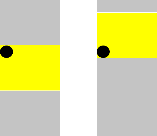
Image A: initial state before translation, Image B: state after translation.
Think of the yellow box as the coordinate system, the black spot as the point of origin. Say I want to translate the coordinate system so that the point of origin will be bottom-left instead of top-left, I just need to shift the yellow box (coordinate system) up, notice the black dot still retains its position, only the coordinate was shifted. In this case of drawing a speedometer, I want to translate the canvas so the point of origin will be on the center of the canvas (also taking into account the RenderObject offset).
Drawing speedometer ticks
For this roadblock, the questions I asked myself were: How can I draw a half-circle?, How do I achieve drawing the ticks to follow through the circumference of the half-circle?.
- A circle has a total of 360° around the circle, so for a half-circle, it will be 360°/2 which is 180°. So to draw a half circle we'll start from 0° from center-left to 180° center-right, but I want to draw ticks not just a line through the circle, which leads to the second point.
- By dividing the total degree for a half-circle by the number of ticks, the sector angle for a unit tick is gotten. (180°/30=6°). Flutter canvas has a method
drawLine(Offset p1, Offset p2, Paint paint)which draws a line from the specified start coordinate (p1) to the end coordinate (p2). This lead me to another problem, how do I get the start and end coordinate, so I googled the formula for getting coordinates of a circle given its angle. I then define two crucial methods inMathsMixinto solve this. I'll talk more about them soon, for now just know the purpose of these functions is to get the x, y coordinates for a given angle.
Calculating the coordinate for a given angle
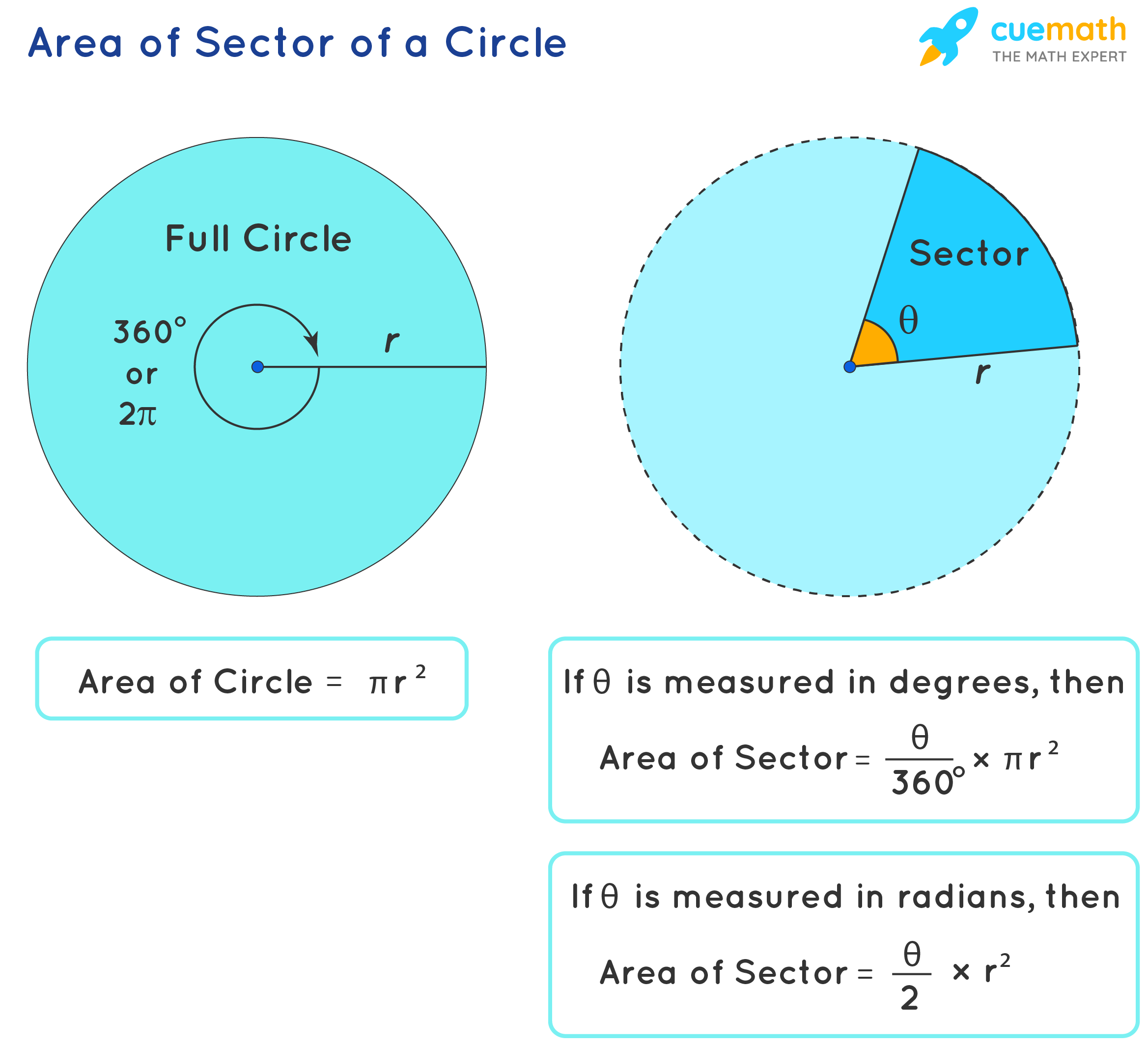
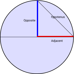 The formula for calculating the x and y coordinate of a circle given an angle is
 x = r sin(radian) and y = r cos(radian) respectively. Remember the SOH CAH TOA rule in trigonometry? sineΘ = opposite/hypotenuse, cosineΘ = adjacent/hypotenuse and tangentΘ = opposite/adjacent, please refer to the image above. The intuition is, given any angle in the first and second quadrant of the circle; for the x-axis: we want to find points between opposite and the hypotenuse within the circumference and the tick length; as such we take the sine function of the angle and multiply by the radius, as for y-axis: we want to find points between the adjacent and hypotenuse within the circumference and the tick length, so we take cosine function of the angle and multiply by the radius. Here's the implementation of these methods:
double computeVerticalPoint(double sectorLength, double radius) {
    // The reason i added 90° to the sector length is
    //The ticks follow through the circumference of the circle not the center of the circle,
    // The angle is then converted from degree to radian
    final angle = convertToRadian(sectorLength + 90);

    return radius * math.cos(angle);
  }

  double computeHorizontalPoint(double sectorLength, double radius) {
    // The reason i added 90° to the sector length is
    //The ticks follow through the circumference of the circle not the center of the circle,
    // The angle is then converted from degree to radian
    final angle = convertToRadian(sectorLength + 90);

    //To get x-coordinate from center-left to center-right we use negative radius
    // as opposed to starting from center-right
    return -radius * math.sin(angle);
  }

 double convertToRadian(double degree) {
    return degree * math.pi / 180;
  }
Algorithm for drawing speedometer ticks
Here's the process I followed:
- For each tick index ranging 0 to 30
- Set sector length, which is the unit sector angle × current tick index (6° × index)
- Set the tick length, for every 5 ticks make it a bit longer
- Set the line start point x, y coordinate using the methods we created passing in sector length and radius subtracted by tick length.
- Set line end point x, y coordinate using the methods we created passing in sector length and radius.
- Initialise color ratio, which is a data class that contains a list of colors and their stop point.
- The actual line is drawn by calling
canvas.drawLine()passing in the start and end coordinate and the paint object.canvas.drawLine() tells the canvas: Hey, go to point 1, then draw a line to point 2 , then set a
SweepGradientshader (A shader is used when stroking or filling a shape).
They say: "a picture is worth a thousand words", in our case though, "a code is worth a thousand explanation" so I'll just show you the code:
 void _drawSpeedometerTicks(
    Canvas canvas,
    Offset offset,
    double unitArc,
    double radius,
  ) {
    for (int i = 0; i < numberOfPoints + 1; i++) {
      final sectorLength = (unitArc * i);

      final tickLength = (size.width) * (i % 5 == 0 ? .15 : .08);

      final Offset startPosition = Offset(
          computeHorizontalPoint(sectorLength, radius - tickLength),
          computeVerticalPoint(sectorLength, radius - tickLength));

      final Offset endPosition = Offset(
          computeHorizontalPoint(sectorLength, radius),
          computeVerticalPoint(sectorLength, radius));

      final colorRatio = colorWithRatio(pointerPoint, majorColor: _color);
      canvas.drawLine(
        endPosition,
        startPosition,
        Paint()
          ..shader = SweepGradient(
            colors: colorRatio.colors,
            stops: colorRatio.ratio,
            endAngle: 2 * math.pi,
            startAngle: math.pi,
            tileMode: TileMode.mirror,
          ).createShader(
            Rect.fromCircle(center: const Offset(0, 0), radius: radius),
          )
          ..style = PaintingStyle.stroke
          ..strokeWidth = 4,
      );
    }
  }
That was a lot to cover hopefully you followed through my thought process painting the speedometer ticks. Next we see how to draw the pointer.
Drawing the pointer
Drawing the pointer was a bit easy, i'll just show you the code and add some comments to explain what each line of code does:
  void _drawPointer(double radius, Canvas canvas) {
    /// unitArc is 180 degree/[numberOfPoints]
    /// [pointerPoint] is a field level variable to track where the pointer is currently pointing to
    // is currently on. More on this when we talking about gestures
    final pointerAngle = unitArc * pointerPoint;

    /// define a paint for the pointer handle
    final paint = Paint()
      ..color = Colors.blueGrey[500]!
      ..style = PaintingStyle.stroke
      ..strokeWidth = 4;

    /// set the start position using the method we created to get the
    /// start coordinates, the reason for subtracting 20 from radius
    /// is to give the pointer a bit padding from top
    final Offset startPosition = Offset(
        computeHorizontalPoint(pointerAngle, radius - 20),
        computeVerticalPoint(pointerAngle, radius - 20));

     /// Set the end position to the center of the circle
    /// the reason i can use Offset(0,0) as the center is because i translated
    /// the canvas to the center initially
    const Offset endPosition = Offset(0, 0);

    /// draw the line
    canvas.drawLine(startPosition, endPosition, paint);

    // draw the larger circle, color it grey and position it center of the circle
    canvas.drawCircle(
      const Offset(0, 0),
      15,
      Paint()
        ..color = Colors.blueGrey[500]!
        ..strokeWidth = 5,
    );

     // draw the inner circle, color it amber and position it center of the circle
    canvas.drawCircle(
      const Offset(0, 0),
      8,
      Paint()
        ..color = Colors.amber
        ..strokeWidth = 5,
    );
  }
Drawing the slider
As with the tracker, i'll just show the code and add some comments
void _drawSlider(Canvas canvas) {
    var curveRadius = const Radius.circular(30);

    // I want the slider to be a bit below the speedometer hence the topMargin here
    final topMargin = size.height * .2;

   /// the radius will be used when drawing the slider
    var radius = size.width / 2;

    /// The [_trackerPath] is a field level variable because it's needed for gesture detection
    /// The path is instructed to draw a rounded rectangle from center-left to center-right
    /// Because our point of origin is 0,0 we want to start from negative radius to positive radius
    _trackerPath = _trackerPath
      ..addRRect(
        RRect.fromRectAndCorners(
          Rect.fromPoints(
            Offset(-radius, topMargin + 10),
            Offset(radius, topMargin),
          ),
          topLeft: curveRadius,
          topRight: curveRadius,
          bottomLeft: curveRadius,
          bottomRight: curveRadius,
        ),
      );

   // set colorRatio which is a data class that contains the color and stops
    final colorRatio = colorWithRatio(pointerPoint, majorColor: _color);

    // This line instructs canvas to draw the trackerPath
    canvas.drawPath(
      _trackerPath,
      Paint()
        ..shader = LinearGradient(
          colors: colorRatio.colors,
          stops: colorRatio.ratio,
        ).createShader(
          Rect.fromCenter(
            center: const Offset(0, 0),
            width: size.width,
            height: size.width,
          ),
        )
        ..strokeWidth = 4
        ..strokeCap = StrokeCap.round
        ..style = PaintingStyle.stroke,
    );

    // This line instructs the canvas to draw the bigger circular knob
    // the [knobPosition] is a field level variable responsible for tracking current knob position
    canvas.drawCircle(
      Offset(knobPosition.dx, topMargin + 5),
      20,
      Paint()
        ..color = Colors.blueGrey[500]!
        ..strokeWidth = 5,
    );

    // This line instructs the canvas to draw the smaller circular knob
    // the [knobPosition] is a field level variable responsible for tracking current knob position
    canvas.drawCircle(
      Offset(knobPosition.dx, topMargin + 5),
      15,
      Paint()..color = Colors.amber,
    );
  }
Adding interactiveness to the speedometer slider
I started by defining some top level variables
/// Slider path
  var _trackerPath = Path();

  /// Tracks the current knob position
  Offset knobPosition = const Offset(0, 0);

  late final DragGestureRecognizer dragGestureRecognizer;
  late final TapGestureRecognizer tapGestureRecognizer;

  /// Tracks the current tick the pointer is pointing to
  double pointerPoint = numberOfPoints / 2;

  _RenderCustomSlider({MaterialColor? color})
      : super(textDirection: TextDirection.ltr, alignment: Alignment.center) {
    dragGestureRecognizer = PanGestureRecognizer()
      ..onStart = _dragStart
      ..onEnd = _dragEnd
      ..onUpdate = _dragUpdate;
    tapGestureRecognizer = TapGestureRecognizer()..onTapDown = _tapDown;
    _color = color;
  }
Next i override hitSelfTest and handleEvent.
 @override
  bool hitTestSelf(Offset position) {

    var radius = (size.width / 2);

    /// From the official documentation: The caller is responsible for transforming position from
    ///global coordinates to its location relative to the origin of this RenderBox.
    position = position.translate(-radius, -(size.height / 2));

     /// I'm checking if the hit/touch position is within the slider's tracker path bounds.
    return _trackerPath.contains(position);
  }

  @override
  void handleEvent(PointerEvent event, covariant HitTestEntry entry) {

    /// Check to see if the pointer event is the type of event i want to handle
    if (event is PointerDownEvent) {
      /// i add the pointers to the tap and drag gesture recogniser, they are responsible
      /// for handling the events
      tapGestureRecognizer.addPointer(event);
      dragGestureRecognizer.addPointer(event);
    }
  }
So far i've implemented two crucial method for handling gestures, the first is to make sure gesture is accepted only if it's within the slider's bound, the second is to handle the event and delegate to the gesture recognisers. Next is to implement gesture recognisers callback methods: onTapDown() for TapGestureRecognizer, onUpdate() for PanGestureRecognizer.
Implementation of callback methods
Before implementing callback methods, one final roadblock i met was how to update the pointer, to point to the correct tick in relation to the knob current position. The answer to that was defining another helper method in MathsMixin to help get the correct pointer position from the current knob position.
 double pointFromRadius(double radius) {
    return (math.pi / numberOfPoints) * radius;
  }
The callback methods code is pretty clear on what they do:
void _dragUpdate(DragUpdateDetails details) {
    final position = details.localPosition;

    if (_notWithinBound(position)) return;

    _updateKnobAndPointerPosition(position);

    markNeedsPaint();
  }

  void _tapDown(TapDownDetails details) {
    if (_notWithinBound(details.localPosition)) return;

    _updateKnobAndPointerPosition(details.localPosition);

    markNeedsPaint();
  }

  bool _notWithinBound(Offset position) =>
      position.dx > size.width || position.dx < 0;

  void _updateKnobAndPointerPosition(Offset position) {
    knobPosition = position.translate(-(size.width / 2), -(size.height / 2));

    pointerPoint = pointFromRadius(position.dx);
  }
The full code can be found in this dart pad link:.
In conclusion this might not be the best solution for this particular challenge, but i hope this article has imprinted the idea of breaking down difficult challenges into smaller components and solve individually. This article merely contains my thought process and how i tackled each road block i faced.
As usual please let me know your thoughts in the comment section, feedbacks are important to me.